Constructing Models
Segmentation and Classification
TBA
Meshing
An important step in any modeling endeavor is the generation of discrete representations of the modeling domain. For simple domains we use mesher. For mesh management meshtool is provided.
Region definition
Active and passive electro-mechanical tissue properties vary throughout the heart. Even under perfectly healthy conditions, action potential shape and duration are variable within the myocardium or conductivities are different between regions of the heart which is reflected in a heterogeneity in conduction velocities. These gradients are due to differences in the intrinsic makeup of cells, changes In general, the exact variation of these properties throughout the heart cannot be determined, however, basic variations of various properties such as AP shape and duration can be measured and such data can be used to characterize the spatial variation of these properties for different regions. For instance, AP shapes can be characterized for cells taken from epicardial, midmyocardial or endocardial tissue, from basal or apical tissue, or from the left or right ventricle.
In computer models mechanisms must be provided to take these known spatial gradients into account.
The main approach implemented in CARPentry relies upon the explicit definition of regions
to which tissue properties can be assigned.
Regions can be formed by defining a set of finite element entities (elements or nodes)
comprising a region. Every finite element entity carries at least one tag
which can be used for region definitions.
If no explicit regions are defined, entities belong to the default region.
There are two distinct approaches to region definition
referred to as Mesh-based tagging and Dynamic tagging.
Mesh-based tagging
Properties are assigned to regions as defined by a set of tags. The properties are assigned homogeneously to the entire region.
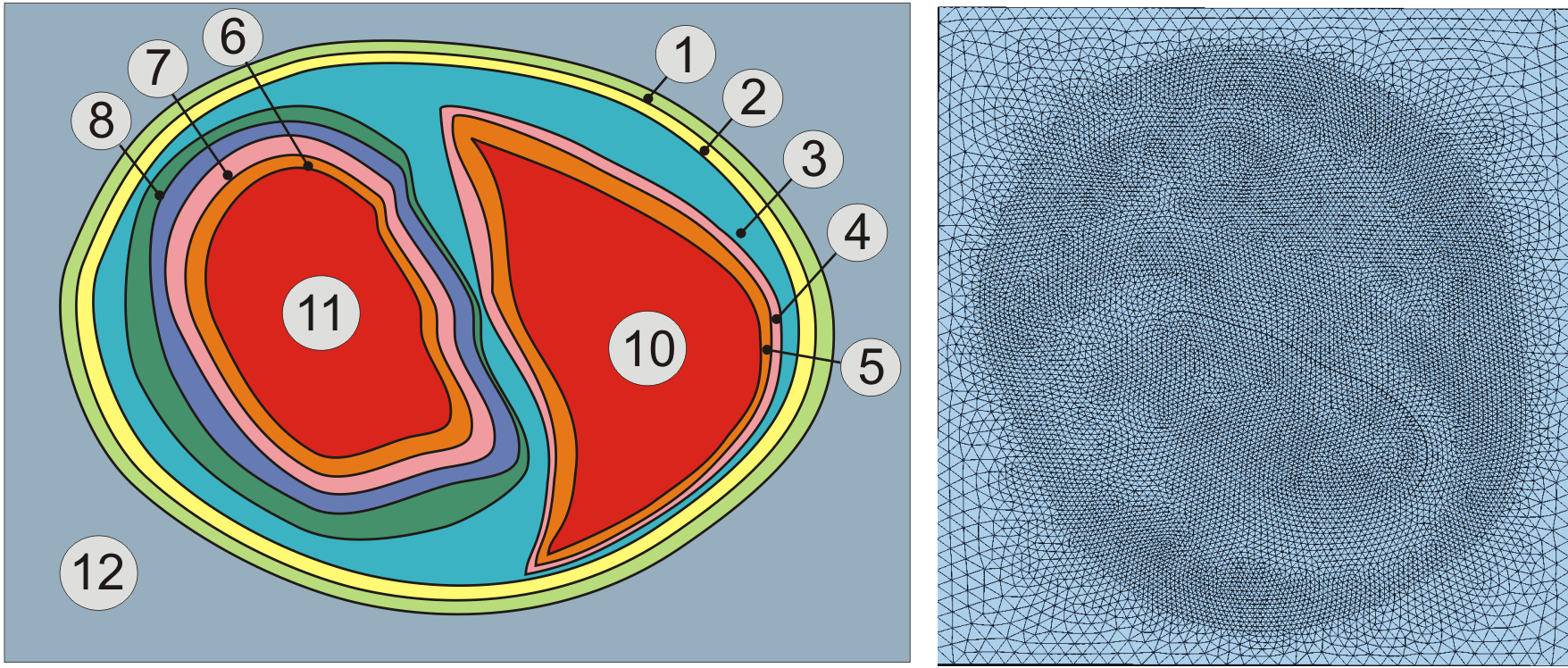
Fig. 3 Assignment of region tags in a rabbit biventricular slice model.
Dynamic tagging
Dynamic tagging can be used for defining regions on the fly by intersecting geometric primitives
such as spheres, cylinders or blocks with a given mesh.
Users may relabel elements based on specifying a volume and retagging all elements
within the volume, or specifying a list of elements.
The number of user regions to be retagged is controlled by numtagreg and
each region is part of the array tagreg[Int].
With intersecting volumes, the highest region tag takes effect.
For each user-defined tag region, the following fields are defined.
| Field | Type | Description |
|---|---|---|
| tag | int | relabelled tag value |
| name | string | label |
| type | int | volume to define (1=sphere,2=block,3=element list) |
| elemfile | string | file with list of elements to retag |
| p0 | float[3] | center of sphere or LL corner of bounding box |
| p1 | float[3] | UR corner of BB |
| radius | float | radius of sphere |
The use of this dynamic tagging feature is elucidated in the Region tagging tutorial.
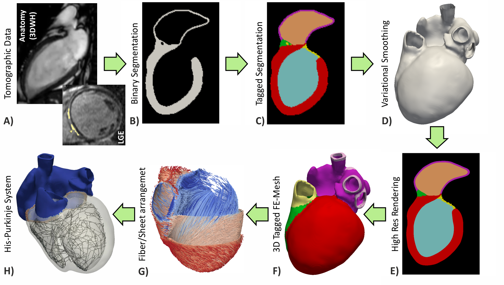
Fig. 4 Workflows for building anatomically accurate models of the heart typically consist of the following stages: A) Tomographic image stacks based on MRI or CT are acquired to capture anatomy in a given state. Typically, a 3D whole-heart (3DWH) snapshot is taken during diastasis or close to an end-diastolic configuration. Depending on the assumed pathology, often additional scan are available to delineate infarcted tissue (late gadolinium enhancement (LGE) MRI) or fibrosis (T1 mapping). B) 3D image stacks are segmented to delineate the heart from the torso background. C) A more detailed voxel classification is performed to label the various anatomical regions of the heart. Labels are also of pivotal importance for defining the in-silico setup at later processing steps. D) Clinical imaging data tend to be of lower anisotropic resolution and as such are not directly suitable for anatomical mesh generation. Variational smoothing methods are often employed to reduce the jaggedness of the implicit surfaces in the raw segmented image data. E) The smoothed discrete surface representation of the heart is re-rasterized at a high isotropic resolution that is suitable as input for voxel-based mesh generation software. F) 3D finite element meshes are generated that also preserves labeling information added at stage C). G) Tissue properties such as the orientation of local fiber architecture is added, either by rule-or atlas-based methods [1] (Jason Bayer et al), or by mapping of additional information contained in complementary image stacks such as e.g. diffusion-tensor MRI scans. H) Additional features such as topological representations of the His-Purkinje system are mapped onto the 3D FE mesh.
| [1] | Bayer JD, Blake RC, Plank G, Trayanova NA. A Novel Rule-Based Algorithm for Assigning Myocardial Fiber Orientation to Computational Heart Models, Ann Biomed Eng 40(10):2243-54, 2012. [PubMed] |