Pre- and Post-Processing Tools
In addition to using CARPentry directly for pre- and post-processing a number of specialized standalone tools is also available for specific purposes. The most widely used ones are summarized below.
Mesh generation (mesher)
Section author: Gernot Plank and Aurel Neic
Introduction
mesher is a program for generating simple regular FE meshes. It can also produce element tag regions
and fiber definitions during element generation.
Usage
The most important parameters of mesher are
- size : Set the size of the mesh in each axis direction.
- resolution : Set the resolution of the mesh in each axis direction.
- bath : Set the bath size in each axis direction. Negative sizes denote a bath on both sides.
- fibers : Set fiber rotation.
- mesh : Set output mesh name.
The unit of the size and resolution parameters is centimeters, while the unit of the resolution is set in micrometers.
Fiber orientation is assigned based on following assumptions:
- The negative z axis is the transmural direction.
- The positive y axis is the apico-basal direction.
- The positive x axis is the circumferential direction.
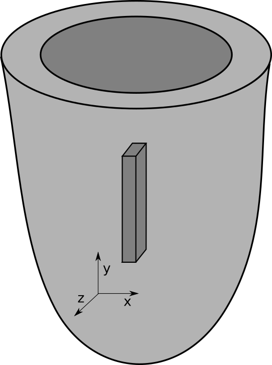
Fig. 7 Convention for the wedge orientation.
Example
The following example creates a myocardial slab of dimensions 0.05 x 0.6 x 0.3 cm immersed in a bath of 0.02 cm on each side:
$ bin/mesher \\
-size[0] 0.05 \\
-size[1] 0.6 \\
-size[2] 0.3 \\
-bath[0] -0.02 \\
-bath[1] -0.02 \\
-bath[2] -0.02 \\
-resolution[0] 100.0 \\
-resolution[1] 100.0 \\
-resolution[2] 100.0 \\
-mesh block
By default, the geometry’s center is located at (0,0,0). As specified, the bounding box of the intracellular domain is
Bbox:
x: (      -250.00 ,       250.00 ), delta 500.00
y: (     -3000.00 ,      3000.00 ), delta 6000.00
z: (     -1500.00 ,      1500.00 ), delta 3000.00
while the bounding box of the overall mesh is
Bbox:
x: (      -450.00 ,       450.00 ), delta 900.00
y: (     -3200.00 ,      3200.00 ), delta 6400.00
z: (     -1700.00 ,      1700.00 ), delta 3400.00
Rule-based fibers can be added with the parameters in the fibers parameter structure. In the previous
example, fiber rotation can be added with:
-fibers.rotEndo 60 \\
-fibers.rotEpi -60 \\
-fibers.sheetEndo 90 \\
-fibers.sheetEpi  90 \\
The resulting geometry is:
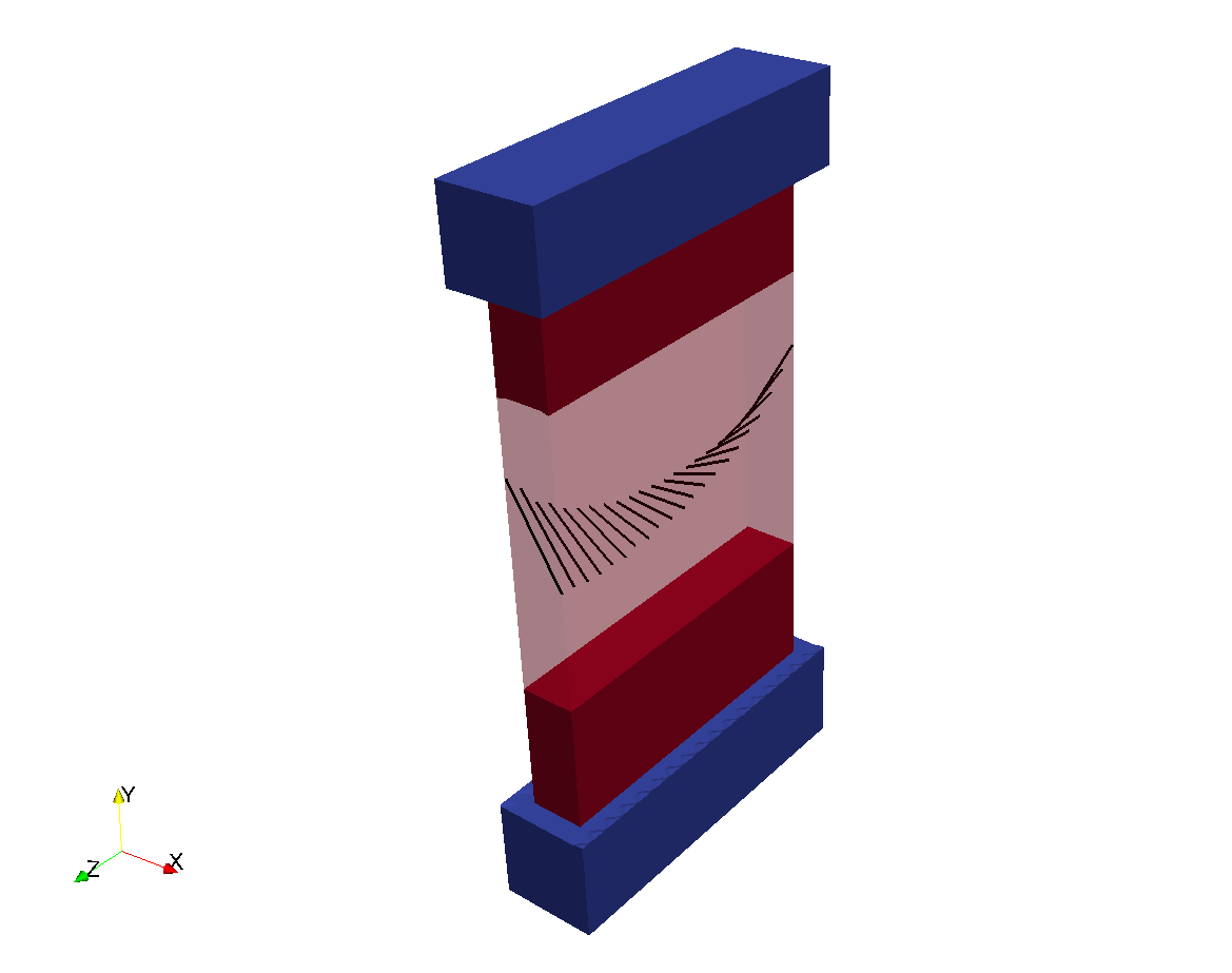
Fig. 8 A slab mesh produced by mesher.
Tag regions
By default, element tag region 0 is assigned to the bath and region 1 is assigned to the myocardium.
Additional regions can be assigned via regdef parameters. A regdef parameter defines a geometric
shape. Elements inside this shape are assigned a given element tag.
The supported region definition shapes are:
$ mesher +Help regdef[0].type

regdef[0].type:
    how to define region

    type:   Int
    default:(Int)(0)
    menu: {
            (Int)(2)        cylinder
            (Int)(1)        sphere
            (Int)(0)        block
    }
The following example shows a minimal definition of a block region:
-numRegions      1 \\
-regdeg[0].type  0 \\
-regdef[0].tag   TAG \\
-regdef[0].p0[0] P0X \\
-regdef[0].p0[1] P0Y \\
-regdef[0].p0[2] P0Z \\
-regdef[0].p1[0] P1X \\
-regdef[0].p1[1] P1Y \\
-regdef[0].p1[2] P1Z
Mesh Management (meshtool)
Submesh extraction
Section author: Aurel Neic
With the “extract mesh” mode, a submesh can be extracted from a mesh based on tag regions. The mode’s parameters are as following:
$ meshtool extract mesh

Mesh extract error: Insufficient parameters provided.
extract mesh: a submesh is extracted from a given mesh based on given element tags
parameters:
-msh=<path>         ... (input) path to basename of the mesh to extract from
-tags=tag1,tag2     ... (input) ","-seperated list of tags
-ifmt=<format>      ... (optional) mesh input format. may be: carp_txt, carp_bin, vtk, vtk_bin, mmg, stellar
-ofmt=<format>      ... (optional) mesh output format. may be: carp_txt, carp_bin, vtk, vtk_bin, vtk_polydata, mmg, stellar
-submsh=<path>      ... (output) path to basename of the submesh to extract to
Therefore a typical call would be:
meshtool extract mesh -msh=/home/aneic/meshes/TBunnyC/mesh/TBunnyC -submsh=TBC_125 -tags=125
Both input and output mesh formats are the default CARP-text formats. In addition to the submesh, meshtool also writes two *.nod and *.eidx files. These hold the node and element mappings between the submesh and the original mesh and are needed by modes that relate submeshes with their associated meshes (e.g. the “insert” and “map” modes).
Surface extraction
Meshtool offers a potent interface for mesh surface extraction. The mode’s help description is:
$ meshtool extract surface

Surface extract error: Insufficient parameters provided.
extract surface: extract a sequence of surfaces defined by set operations on element tags
parameters:
-msh=<path>           ... (input) path to basename of the mesh
-surf=<path>          ... (output) list of names associated to the given operations
-op=operations        ... (optional) list of operations to perform. By default, the surface of the full mesh is computed.
-ifmt=<format>        ... (optional) mesh input format. may be: carp_txt, carp_bin, vtk, vtk_bin, mmg, purk, stellar
-ofmt=<format>        ... (optional) mesh output format. may be: carp_txt, carp_bin, vtk, vtk_bin, vtk_polydata, mmg, stellar
-edge=<deg. angle>    ... (optional) surface elements connected to sharp edges will be removed. A sharp edge is defined
                          by the nodes which connect elements with normal vectors at angles above the given threshold.
-coord=<xyz>:<xyz>:.. ... (optional) restrict surfaces to those elements reachable by surface edge-traversal
                          from the surface vertices closest to the given coordinates.
                          If -edge= is also provided, sharp edges will block traversal, thus limit what is reachable.
-size=<float>         ... (optional) surface edge-traversal is limited to the given radius from the initial index.

The format of the operations is:
tagA1,tagA2,..[+-:]tagB1,tagB2../tagA1,..[+-:]tagB1../..
Tag regions separated by "," will be unified into submeshes. If two submeshes are separated by "-", the rhs mesh surface
will be removed from the lhs surface (set difference). Similarly, using "+" will compute the surface union.
If the submeshes are separated by ":", the set intersection of the two submesh surfaces will be computed.
Individual operations are separated by "/".
The number of names provided with "-surf=" must match the number of operations. If no operations are provided,
the surface of the whole geometry will be extracted. Individual names are separated by ",".
Further restrictions can be added to the surface extraction with the -edge= , -coord= , -size= options.
The surface of a whole mesh can therefore be extracted with:
$ meshtool extract surface -msh=TBC_i -surf=TBC_i
Reading mesh: TBC_i.*
Reading elements in text CARP format:                       [====================]
Reading points in text CARP format:                         [====================]
Reading fibers (2 directions) in text CARP format:          [====================]
Done in 7.47963 sec
Computing surface 1/1
Done in 0.870943 sec
Writing surface TBC_i.surf
Writing vertices TBC_i.surf.vtx
Writing neubc TBC_i.neubc
Done in 0.103977 sec
Here, a surface TBC_i.surf is generated for the mesh TBC_i.elem, TBC_i.pts. Further, *.surf.vtx file (holding the unique surface vertices) and a *.neubc file (containing data needed for mechanics Neumann boundary conditions) are written. If “-ofmt” is specified, the surface is also outputted as a standalone mesh in the desired format.
More complex surfaces can be extracted with set operations on tag sets. For this, the “-op” parameter needs to be specified. In the following example, the set intersection of the surface of tag region 125 and the surface of tag region 150 is computed:
meshtool extract surface -msh=TBC_i -surf=TBC_i_125:150 -op=125:150
The result looks like:
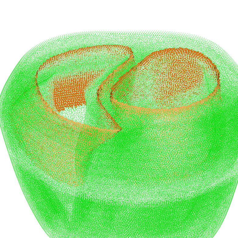
Fig. 9 The surface intersection between tags 125 and 150.
Finally, surfaces can be computed by traversing the surface nodes connected to a given node list. Sharp edges can be set to block surface traversal. The “-edge” parameter defines the sharp edge angle threshold between surface elements. For example the base of the TBunnyC myocardium can be computed as following:
$ meshtool extract surface -msh=TBC_i -surf=TBC_i.top -idx=506478 -edge=10
Reading mesh: TBC_i.*
Reading elements in text CARP format:                       [====================]
Reading points in text CARP format:                         [====================]
Reading fibers (2 directions) in text CARP format:          [====================]
Done in 7.49793 sec
Setting up n2e / n2n graphs ..
Computing connectivity graphs:                              [====================]
Computing surface 1/1
Done in 0.859898 sec
Computing connectivity graphs:                              [====================]
Nodes reached:                                              [====================]
Writing surface TBC_i.top.surf
Writing vertices TBC_i.top.surf.vtx
Writing neubc TBC_i.top.neubc
Done in 0.460613 sec
The result looks like:
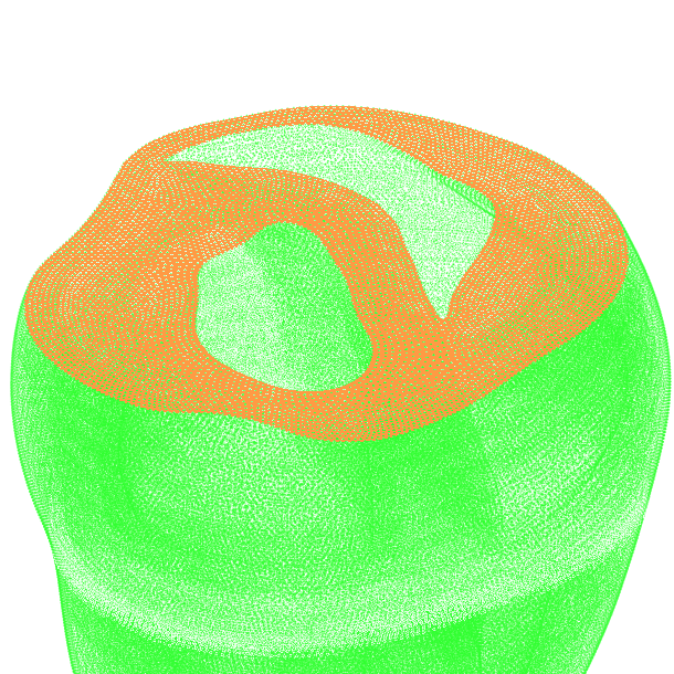
Fig. 10 The surface of the TBunnyC myocardium base.
Meshtool query function
Query list of tags
meshtool query tags -msh=MESHNAMEWITHOUTEXTENSION -ifmt=%
where % is either carp_txt, carp_bin, vtk, vtk_bin depending on the mesh to be checked. In case you are checking a vtk file make sure that the name of the tag variable in the vtk file is “elemTag”. This command prints a list of all tags comprised in the mesh. An example output is shown below:
Reading mesh: /home/plank/meshes/TBunnyC2/mesh/TBunnyC2.*
Reading elements in text CARP format:                       [====================]
Reading points in text CARP format:                         [====================]
Reading fibers (2 directions) in text CARP format:          [====================]
Done in 0.638392 sec
All tags:
0 1 2 100 101 102 103 104 105 106 150 151 152 153 154 155 156 200 201 202 203 204 205 206
Extracting myocardium ..
Done in 0.220971 sec
Myocardium tags:
100 101 102 103 104 105 106 150 151 152 153 154 155 156 200 201 202 203 204 205 206
Retrieve resolution statistics of a mesh
Mean and variability of edge lengths in a FEM mesh is an important metric as spatial resolution influences to some degree numerical computation. An edge lengths statistics is retrieved by
meshtool query edges -msh=MESHNAMEWITHOUTEXTENSION -ifmt=%
This plots a text-based edge length histograms to the console:
Reading mesh: /home/plank/meshes/TBunnyC/mesh/TBunnyC.*
Reading elements in binary CARP format:                     [====================]
Reading points in binary CARP format:                       [====================]
Done in 2.92863 sec
Setting up n2e / n2n graphs ..
Computing connectivity graphs:                              [====================]
Done in 3.47954 sec

Number of connections

Average: 13.8348, (min: 4, max: 31)

 == Histogramm ==

         --------------------------------------------------------------------------------------------
   +0.26 |                                   *                                                      |
         |                               *****                                                      |
   +0.22 |                             **     *                                                     |
         |                           **       *                                                     |
         |                       ****         **                                                    |
         |                     ***             *                                                    |
   +0.15 |                     *               *                                                    |
         |                    **                *                                                   |
         |                    *                 *                                                   |
         |                   **                 **                                                  |
   +0.07 |                   *                   *                                                  |
         |                  **                   *                                                  |
         |                  *                    ***                                                |
         |               ****                      *****                                            |
   +0.00 |****************                             ****************************************     |
         --------------------------------------------------------------------------------------------
          4.0             8.9            13.7            18.6            23.4            28.3

Edge lengths

Average: 326.493, (min: 37.0675, max: 1840.16)

 == Histogramm ==

         --------------------------------------------------------------------------------------------
   +0.53 |                                                                                          |
         |        **                                                                                |
   +0.46 |        ***                                                                               |
         |       ** *                                                                               |
         |       *  **                                                                              |
         |       *   **                                                                             |
   +0.30 |      **    *                                                                             |
         |      *     **                                                                            |
         |      *      **                                                                           |
         |     **       *                                                                           |
   +0.15 |     *         *                                                                          |
         |     *         **                                                                         |
         |    *           **                                                                        |
         |  ***            ****                                                                     |
   +0.00 |***                 *****************************************************************     |
         --------------------------------------------------------------------------------------------
         37.1           361.2           685.4          1009.5          1333.7          1657.8
Retrieve mesh quality statistics
A statistics on mesh quality can also be retrieved using the query command. So far, quality calculation is only implemented for tetrahedral elements. In tissue scale simulations it is a frequent source of errors that meshes are generated without properly checking element quality.
meshtool query quality -msh=MESHNAMEWITHOUTEXTENSION -ifmt=%
Shown below is a mesh quality histogram as output to the console. The quality metric outputs the quality of an element on a scale ranging from 0 to 1 where 0 indicates best quality and 1 is poorest quality.
Reading mesh: /home/plank/meshes/TBunnyC/mesh/TBunnyC.*
Reading elements in binary CARP format:                     [====================]
Reading points in binary CARP format:                       [====================]
Done in 0.491191 sec
Computing mesh quality ..
Done in 0.202803 sec

-------- mesh statistics ---------
Number of elements: 5082272
Number of nodes: 862515

-------- element quality statistics ---------
Used method: tet_qmetric_weightedShapeDist with 0 == best, 1 == worst
Min: 3.98307e-05 Max: 0.873355 Avrg: 0.125359

Histogramm of element quality:

         --------------------------------------------------------------------------------------------
   +0.12 |                                                                                          |
   +0.12 |      ****                                                                                |
         |     **  **                                                                               |
         |    **    **                                                                              |
         |    *      *                                                                              |
   +0.09 |   **      **                                                                             |
         |   *        *                                                                             |
         |  **        **                                                                            |
         |  *          *                                                                            |
   +0.07 | **          **                                                                           |
         | *            *                                                                           |
         | *            **                                                                          |
         | *             *                                                                          |
   +0.05 |*              **                                                                         |
         |*               **                                                                        |
         |*                *                                                                        |
         |*                **                                                                       |
   +0.02 |                   **                                                                     |
         |                    **                                                                    |
         |                     ***                                                                  |
         |                       *****                                                              |
   +0.00 |                           ************************************************************** |
         --------------------------------------------------------------------------------------------
          0.0             0.2             0.4             0.5             0.7             0.9
Mesh quality improvement
In the “clean quality” mode, the quality of a mesh can be improved by vertex displacement and by volumetric smoothing. The effectiveness of either methods depends on the reason for the bad element quality (e.g. mesh has been clipped, mesh has been smoothed).
Vertex displacement restores quality for elements that have been “flattened-out”, either explicitly by mesh smoothing, or implicitly by the mesh generation algorithm. It’s drawback is that it destroys surface smoothness.
Vertex smoothing redistributes vertices in equal distance of each other. This improves mesh quality if the mesh has been modified by clipping.
The two methods can be used alone or combined. Depending on the underlying mesh problem, they can complement or act against each other. For example, if the mesh generation algorithm was configured to produce very smooth surfaces, it has probably also produced flat elements at the interfaces of the surfaces. This flat elements can only by improved by vertex displacement which will reduce surface smoothness. Vertex smoothing is not useful for this case, since it would only counter the vertex displacement by restoring surface smoothness.
In the following example, the mesh quality is restored for a LV mesh where an artery has been clipped. Here, mesh smoothing will be generate the main quality improvement. Therefore, the smoothing coefficient (smth=0.3 means that a vertex will be moved 30 percent towards its center-point) and number of iterations (iter=150) are set rather high. Surface files are passed via the “surf” parameter, in order to protect them and their edges (edge detection is turned on via edge=30).
$ meshtool clean quality -msh=OPBG010.cut -thr=0.9 -surf=OPBG010.cut,OPBG010.cut.blood -smth=0.3 -iter=150 -edge=30 -outmsh=OPBG010.cut.cln -ofmt=vtk_bin
Using OpenMP parallelization with 6 threads.
Reading mesh: OPBG010.cut.*
Reading elements in text CARP format:                       [====================]
Reading points in text CARP format:                         [====================]
Reading fibers (1 direction) in text CARP format:           [====================]
Mesh consists of 2191988 elements, 383188 nodes.
Correcting inside-out tets ..
Pass 1: Corrected 0 inside-out elements.
Done in 3.48826 sec
Reading surface: OPBG010.cut.surf
Reading elements in text CARP format:                       [====================]
Reading surface: OPBG010.cut.blood.surf
Reading elements in text CARP format:                       [====================]
Setting up n2e / n2n graphs for mesh surface ..
Computing connectivity graphs:                              [====================]
Setting up line interfaces for mesh surface ..
Computing connectivity graphs:                              [====================]
Computing connectivity graphs:                              [====================]
Done in 5.89264 sec

Checking mesh quality ..
Mesh quality statistics:
min: 6.69769e-05, max: 2.78184, avg: nan
Number of elements above threshold: 1381
Done in 0.15244 sec

Improving mesh ..
Setting up n2e / n2n graphs for mesh ..
Computing connectivity graphs:                              [====================]
Starting with optimization ..
Iter 0: Number of elements left above threshold: 1381
Smoothing progress:                                         [====================]
Smoothing progress:                                         [====================]
Smoothing progress:                                         [====================]
Smoothing progress:                                         [====================]
Iter 1: Number of elements left above threshold: 51
Smoothing progress:                                         [====================]
Smoothing progress:                                         [====================]
Smoothing progress:                                         [====================]
Smoothing progress:                                         [====================]
Iter 2: Number of elements left above threshold: 64
Mesh quality statistics:
min: 6.69769e-05, max: 0.997674, avg: 0.105546
Done in 12.1368 sec
Correcting inside-out tets ..
Pass 1: Corrected 20 inside-out elements.
Pass 2: Corrected 0 inside-out elements.
Writing mesh: OPBG010.cut.cln.*
Writing vtk file in binary format:                          [====================]
Done in 1.15729 sec
The original mesh had element of such a poor quality that the element quality couldn’t even be computed, while the resulting mesh is of useable quality.
The result looks like:
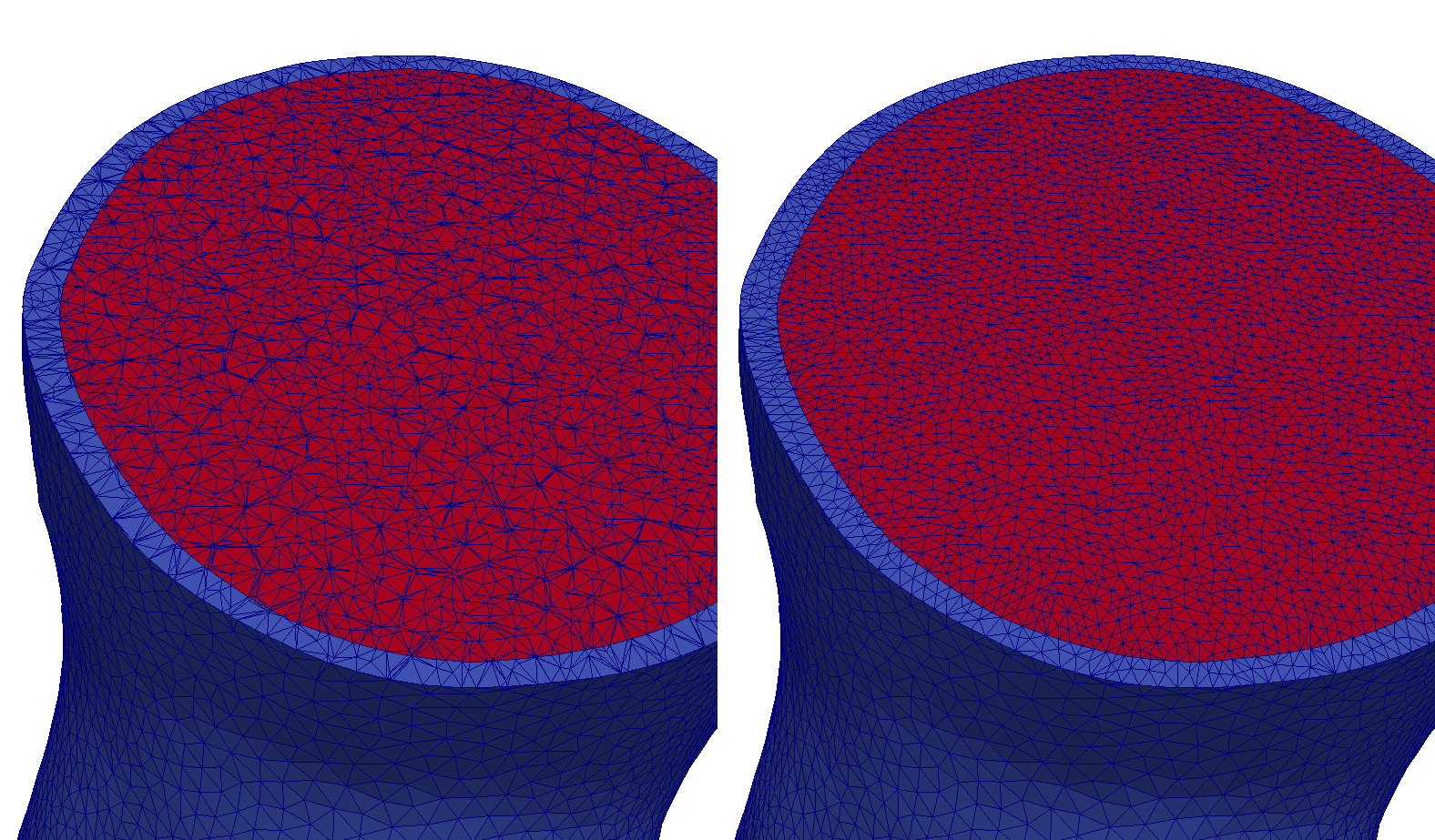
Fig. 11 Comparison between original mesh and imporved mesh for a clipped geometry.
igbutils
For all tools, help is output with the -h option.
igbhead
Operations to perform on the headers of IGB files. Most commonly, it it used to print the header information but can also be usd to modify it. This utility can also be used to change the storage type of the file, or put an IGB header on to ASCII and binary data file.
igbapd
A simple utility to compute action potential durations.
igbops
This utility can perform basic math operations on one or two IGB files. There are preset functions as well as a parser for arbitrary functions. For example, one can difference two IGB files, find maxima over time, or apply a box filter.
igbextract
This is a tool to extract a hyperslab of data from an IGB file. The format of the output can be chosen between ASCII, binary or IGB.
igbdft
This is a tool for simple frequency domain techniques. It contains a limited number of operations which include Butterworth filtering, DFTs, and computing phase.
FEM tools
Tools recognize the -h to display detailed help.
GlElemCenters
Compute the element centers of a nodally defined mesh
GlFilament
Compute phase singularities and filaments.
GlGradient
Compute gradients of grid data and conduction velocities if activation times are used.
GlInterpolate
Interpolate data restitution-protocol-definition, from nodes to element centers or vice versa.
GlRuleFibers
Compute the fibres for a biventricular mesh.
GlTransfer
Transfer data between spatially overlapping grids.