Mesh Generation
carputils provides extensive functionality for the automatic generation of meshes according to geometric shapes. This currently includes:
- 1D cable (
carputils.mesh.Cable) - 2D grid (
carputils.mesh.Grid) - Block/cuboid (
carputils.mesh.Block) - Ring/cylindrical shell (
carputils.mesh.Ring) - Ellipsoidal shell (
carputils.mesh.Ellipsoid)
The carputils.mesh module also provides some utility functions to be
used with the above classes. See the API documentation
for more information. This page provides a general guide to using the mesh
generation code.
Basic Usage
The definition of the mesh geometry is generally done when calling the class constructor. For example, if generating a block mesh of size 2x2x2mm and resolution 0.25mm:
from carputils import mesh
geom = mesh.Block(size=(2,2,2), resolution=0.25)
Note that all dimensional inputs to the meshing classes are in millimetres. Please see individual classes’ documentation, as linked above, for details on the arguments they accept.
To then generate the actual CARP mesh files, there are two approaches depending
on the class being used. The block class, which is actually a wrapper for the
mesher command line executable, requires use of the mesher_opts method
and then for mesher to be called with these arguments. This is done
automatically by carputils.mesh.generate(), which also checks if the same
mesh already exists and only generates a new one if not:
meshname = mesh.generate(geom) # Returns the meshname of the new mesh
The other classes, which generate the mesh in python directly, generate the
mesh files with a call to the generate_carp method:
geom = mesh.Ring(5)
meshname = 'mesh/ring'
geom.generate_carp(meshname)
Note that these classes also support the direct output to VTK with the
generate_vtk and generate_vtk_face methods.
Fibre Orientation
Block objects support the assignment of fibre orientations with the
set_fibres() method, which takes angles in
degrees as arguments:
from carputils import mesh
geom = mesh.Block(size=(2,2,2), resolution=0.25)
geom.set_fibres(0,  # endocardial fibre angle
                0,  # epicardial fibre angle
                90, # endocardial sheet angle
                90) # epicardial sheet angle
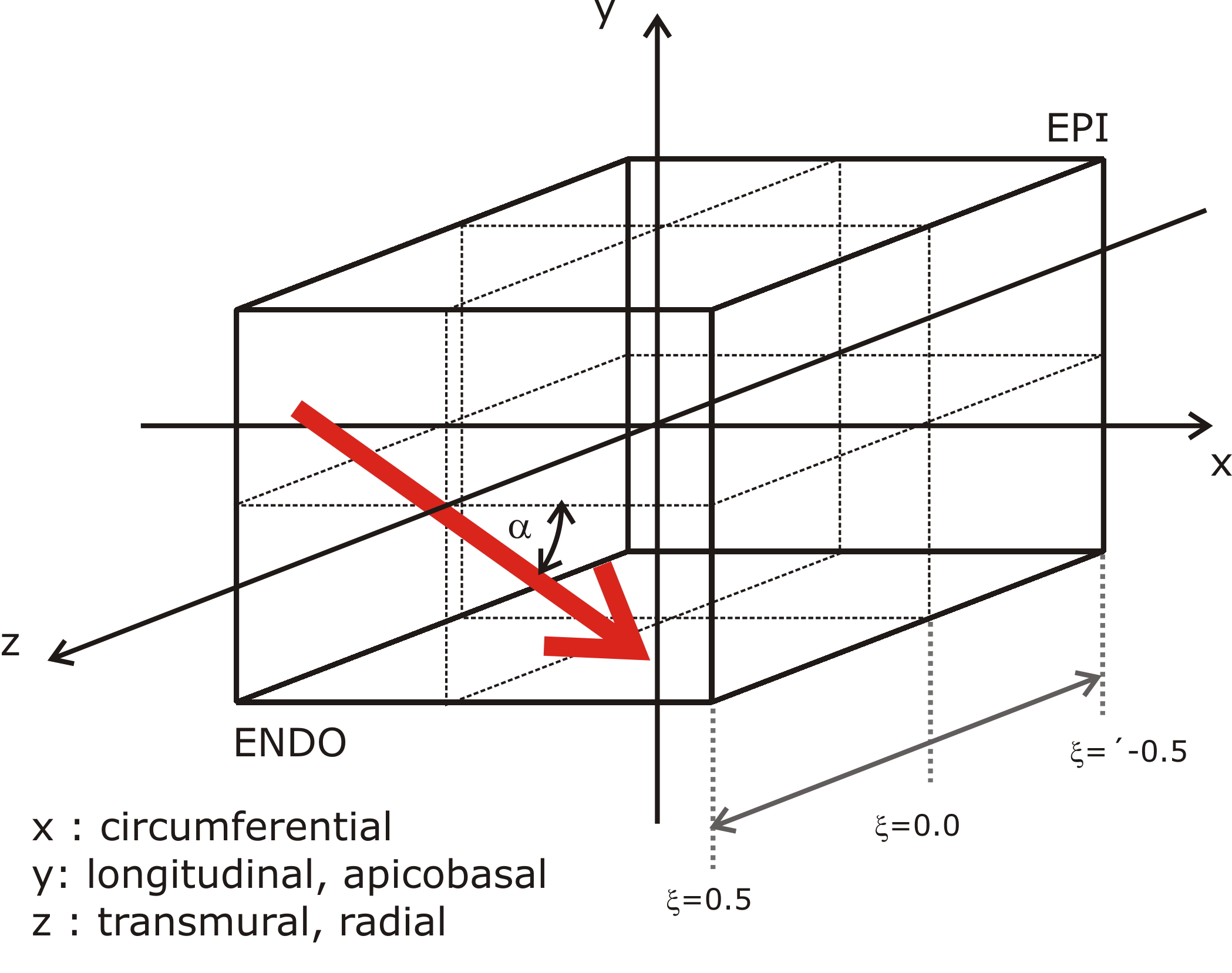
Note that the material coordinates in meshes generated by Block are as
illustrated below. Specifically, the  direction corresponds to the
circumferential direction,
direction corresponds to the
circumferential direction,  corresponds to the apical-basal direction
and
corresponds to the apical-basal direction
and  corresponds to the epi- to endocardium direction.
The other 3D mesh classes take the fibre_rule argument to the constructor,
which should be a function returning a helix angle in radians when passed a
normalised transmural distance (where 0 corresponds to endocardium and 1
corresponds to epicardium):
def rule(t):
    """
    +1 radian endo to -1 radian epi
    """
    return 1 - 2*t

# Or as a one-liner
rule = lambda t: 1 - 2*t

# Then to create a ring with this fibre rule
geom = mesh.Ring(5, fibre_rule=rule)

# Or even more compact
geom = mesh.Ring(5, fibre_rule=lambda t: 1 - 2*t)
The meshing code provides a convenience method for the generation of linear fibre rule in degrees or radians. For example, to generate the common +60 to -60 degree rule:
p60m60 = mesh.linear_fibre_rule(60, -60)
geom = mesh.Ring(5, fibre_rule=p60m60)
The 1D cable mesh always has a constant fibre direction aligned with the cable,
while the 2D grid mesh has a constant fibre direction assigned with the
fibres argument.
Tagging Regions
Block meshes can be tagged using one of three classes:
- An axis-aligned box (
carputils.mesh.BoxRegion) - A sphere (
carputils.mesh.SphereRegion) - A cylinder (
carputils.mesh.CylinderRegion)
See the class documentation for details on the exact arguments they take. They
all, however, take the tag argument, which specifies the tag to be assigned
to the elements inside the region:
geom = mesh.Block(size=(2,2,2))
reg = mesh.BoxRegion((-1,-1,-1), (1,1,0), tag=10)
geom.add_region(reg)
The other classes have tag regions assigned by passing a python function which returns True/False indicating whether a passed point is inside. For example, to assign a tag region to all points for positive x:
geom = mesh.Ring(5)
reg = lambda coord: coord[0] >= 0.0
geom.add_region(2, reg)
Note that the region tag must be passed separately in this case. The region
classes above can also be passed, however note that the tag defined in the
region object’s constructor is ignored in favour of that passed to
add_region.
Boundary Conditions
An additional convenience function
block_boundary_condition() is included to provide for the
easy definition of boundary conditions in block meshes. It uses the size and
resolution information from the geometry object to compute a box that surrounds
only the nodes of interest, and returns a set of CARP command line options. For
example, to define a stimulus on the upper-x side of a block:
geom = mesh.Block(size=(2,2,2))
bc = mesh.block_boundary_condition(geom, 'stimulus', 0, 'x', False)
The other mesh classes do not have an equivalent method, however the other 3D mesh classes offer functionality for the automatic generation of .surf, .neubc and .vtx files corresponding to relevant surfaces on the geometry. For example, with a ring geometry, you may wish to define Dirichlet boundary conditions on the top and bottom of the Ring and Neumann boundary conditions to the inner face. To generate files for these:
geom = mesh.Ring(5)
meshname = 'mesh/ring'
geom.generate_carp(meshname, faces=['inside', 'top', 'bottom'])
Which will generate files named like mesh/ring_inside.neubc.
Constraining Free Body Motion
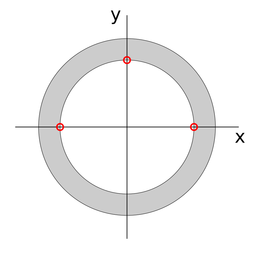
You may also wish to take advantage of the generate_carp_rigid_dbc method,
which generates two vertex files for the purposes of preventing free body
rotation of the mesh. As illustrated in the image below, this includes two
points on the x axis and one on the y axis on the inner surface of the ring or
ellipsoid shell.
The files are generated by:
geom.generate_carp_rigid_dbc('mesh/ring')
which creates the files mesh/ring_xaxis.vtx and mesh/ring_yaxis.vtx. Dirichlet boundary conditions should be set up using these files, where the x axis nodes are fixed in their y coordinate and y axis node is fixed in its x coordinate. The first BC will then prevent free rotation and translation in the y direction, and the second will prevent translation in the x direction.
Implementation Details
Tessellation
An important consideration when generating a mesh in a subclass is how the resulting elements are to be tessellated into tetrahedra, which is done for most practical meshes used with CARP. Code to procedurally generate meshes in subclasses of Mesh3D generally use a combination of prisms and hexahedra to fill the geometry, however care must be taken to ensure that the edges of neighbouring elements match after the tessellation into tetrahedra is performed.
Hexahedra are deliberately tesselated in such a way that a grid of them which are all oriented in the same way will join up well when tessellated. There are two types of prisms available, offering the two possible ways for a prism to be tessellated.
When writing new mesh classes, the following nets provide a guide to the way in which these elements are tessellated. Printing these out and constructing the shapes aids considerably in figuring out how the elements mesh together.

Face Selection
The above nets also label each face. These are used in the mesh classes when generating elements to select particular faces for inclusion in generated surface and vertex files, which are themselves used for setting up boundary conditions in CARP simulations.
The _register_face method of the Mesh3D-derived classes is the way that
faces in the mesh are accumulated:
etype = 'hexa'
face  = 'front'
surface = 'endo'
self._register_face(etype, face, surface)
This will add the front face of the last hexahedron added to the mesh to the
endo surface. It is also possible to pass an exact element index to this
function, which by default just adds the last element of that type that was
added to the mesh.